At the very start of my Masters, my first experiments appeared to show that the histamine H3 receptor inhibited the release of GABA in the neocortex. It turns out, this was all lies. It was all lies because of series resistance, a concept I had vaguely heard of, but didn’t understand. If you’re just starting electrophysiology this post is for you. The hope is that by the end of this post, you will understand series resistance, and you’ll understand why it is extremely important to monitor it religiously, whether you’re performing voltage clamp or current clamp recordings.
Voltage Clamp
Take Home Points
- The smaller your series resistance is relative to your membrane resistance, the closer the membrane potential will get to your command potential, given enough time. You should aim for your series resistance (after Rs compensation) to be less than 1/10th of your membrane resistance
- The membrane capacitor and the series resistances sets up a low-pass filter for your command voltage. Hence you will be able to voltage clamp faster signals when Rs and Cm are small
- Voltage clamp is never perfect, but it can be good enough. However, if Rs changes during your experiment, all currents you record will change with it, hence you must monitor it, and reject cells when it changes
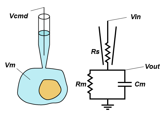 In standard whole-cell voltage clamp, the goal is simple: hold the membrane potential of the cell at the command voltage (Vcmd) and tell the experimenter how much current that required, because it should be equal and opposite to any transmembrane current. However, there is one major thing that is stopping things going to plan: series resistance (Rs). Series resistance is the sum of all the resistances between the electronics in the amplifier and the inside of your cell, but in practice is made up of the resistance in the last dozen microns of the pipette and the junk that blocks up the hole between the pipette and the cell (good rule of thumb, your series resistance should be around 3x the open pipette resistance).
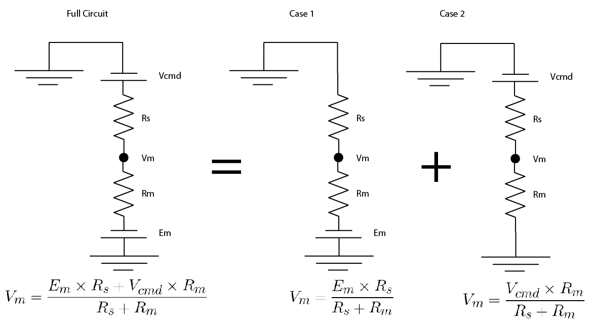
But why does series resistance matter? Because together with the resistance (Rm) and capacitance (Cm) of the membrane, it creates a voltage divider, that is, the voltage you are trying to apply to the cell is divided across Rs and the impedance presented by the combination of Rm and Cm. Even simpler yet, you can think of Rs as limiting the amount of current you can use to charge up the membrane. This means that the actual voltage you get inside the cell (Vout) is given by
Where Vm is the resting membrane potential. As you can see, if Rs is much smaller than Rm, then Vout approaches Vcmd, likewise, if Rs is massive, then Vout approaches Vm. This is where we can see the how the Rs < Rm/10 rule of thumb comes about. If we say Rs = Rm/10, then the above equation becomes:
Which simplifies to:
Which basically says Vout = Vcmd plus a tiny fraction of Vm. As Rs becomes a smaller fraction of Rm, the less Vm contributes to the final membrane potential.
But this voltage divider is a frequency dependent voltage divider, because capacitors let more current through when the voltage across them changes rapidly. And do you know the other word for a frequency dependent voltage divider? A filter, in this case a low-pass filter. The corner frequency of this filter is given by a pretty awful looking equation:
But if Rs is much smaller (about 10x less) than Rm, you can approximate the cut-off frequency of the filter with the much simpler
(A little helpful note, if Rs is in MΩ and Cm is in pF then the answer is in MHz).
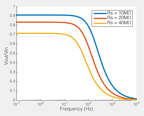
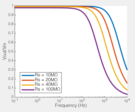
How series resistance creates a low-pass filter. Behaviour of voltage clamp on a cell with Rm=100MΩ, Cm=100pF
To the right you see what this means. If we compare the ratio of the voltage across the cell membrane to the command voltage (Vout/Vin), we can see the effect of Rs on how good out voltage clamp is. Perfect voltage clamp would produce a horizontal line at Vout/Vin = 1, meaning that no matter how fast you tried to change the command voltage, the membrane potential would follow it perfectly. But instead what you see is what I described above: even at very low frequencies (e.g. constant voltages) when the series resistance is high the membrane potential does not even come close to the command voltage. You also see that as Rs increases, the filter becomes more aggressive, meaning that even relative slow voltage changes cannot be achieved. In the case illustrated, of an 100MΩ/100pF cell, when Rs is 40MΩ, you are beginning to fail to voltage clamp at the relatively glacial frequency of 10 Hz.

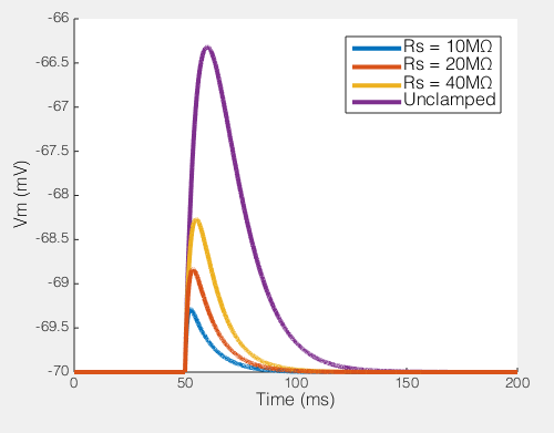
Trying to voltage clamp a synaptic current in a 100MΩ/100pF cell
This may still seem relatively academic at this point, so let me really try to show you what this means. To the right you can see what happens when you try to voltage clamp a modeled synaptic current as Rs increases (the synaptic event is current based, rather than conductance, so it is the same no matter how bad the voltage clamp is). I have flipped the synaptic current, so they’re easy to compare. You see that even in the relatively ideal case of Rs = 10MΩ the measured current is a lot smaller than the real current. In part this is unfair because this current is instantaneously rising (and as the previous figure showed, fast changes are the enemy of any voltage clamp), so note how the decay of the current is relatively well captured in all cases. However, the point is, if you had been performing voltage clamp, and your Rs had changed from 10MΩ to 20MΩ, the current you would have measured would have dropped by about 15%. If you had been washing on a drug at the time, you might think that the drug caused that reduction (which is exactly what happened to me). Hence why I am always a lot more convinced by any long term voltage clamp experiment that shows Rs as a function of time, along with any other measurement (e.g. Fig 1 here).
The EPSP produced by our synaptic current (100pA peak) with different values of Rs
Of course, not only does Rs effect the current you end up recording, but it has big effects on the amount of unclamped voltage generated by any transmembrane current. To the right you see the size of the EPSP our synaptic current would produce in the absence of voltage clamp. In a perfect world this would be a flat line, i.e. the voltage would be clamped. But when Rs = 40MΩ, you can see that the EPSP produced is nearly half the size of the unclamped potential, i.e. this is not voltage clamp at all, but really some weird thing half way between current clamp and voltage clamp.
Finally, it’s worth mentioning that series resistance compensation allows us to minimize all of these effects (but not remove them). Specifically, if you have a real Rs of 20 MΩ, and then you perform series resistance compensation to 75%, then your series resistance will appear to be 5 MΩ. It’s also important to remember that in large cells, you run into space clamp problems, where you are unable to voltage clamp distal parts of the cell (you can think about the distal sites being behind another series resistor, this time formed by the resistance down the cytoplasm of the dendrite), but that is a whole other story.
For me, voltage clamp is no different that most science: you are not measuring perfectly and your measurements are just an approximation of the real thing. The important thing is to know when the approximation is good, and when it is bad, e.g. Voltage clamp recordings from cereballar granule cell (Cm = 5 pF, Rm = 1000MΩ) give you a good approximation of transmembrane current. But even if those good cases, when Rs changes, even a constant transmembrane current will appear to change, and that is really bad.
Below you can adjust the properties of your voltage clamp system, and see how good you voltage clamp should be.
Current Clamp
Take Home Points
- A combination of the pipette capacitance and the series resistance sets up a low-pass filter for membrane voltages
- This filter works at a much higher frequency that the filter effecting voltage clamp
- Again, you should monitor it, as it can change the features of the voltages you are trying to measure
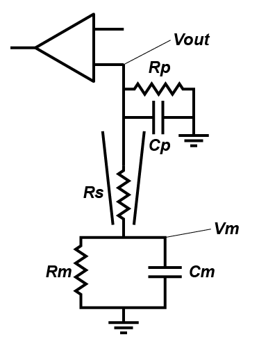 People often forget about the effect of Rs on current clamp recording, outside of bridge balance (which I very much hope you understand, but if you don’t, the simple thing is that when you inject current, it falls across the series resistor, meaning that you record a voltage that is the sum of the transmembrane voltage and the voltage across the series resistance. Bridge balance subtracts that voltage). But in a fashion very similar to in the voltage clamp case, series resistance effects the nature of filter that messes with your ability to record cellular properties. However, in current clamp, the capacitor that is involved is the capacitance formed by the pipette (Cp). Essentially, in current clamp, Rs limits how quickly the cell can charge Cp, which limits your ability to monitor fast voltage changes. The other resistance that is important is the input impedance of the amplifier, which I have labelled Rp. This represents how much current the circuitry in your amplifier draws.
How series resistance effects current clamp recordings. Modeled with Cp = 5pF and Rp = 5GΩ.
Because the capacitor in question is much smaller (Cp < Cm), the frequencies where this filter starts to kick in are much higher, but action potentials are pretty fast voltage transients. As you can see in the figure to the right where we plot the ratio of the recorded voltage to the actual membrane potential (Vout/Vm), in the case where Rs = 100 MΩ, even signals around 100 Hz are being filtered, which will really filter action potentials (remember, the frequency components that make up the action potential are much faster than the rate at which action potentials occur). Furthermore, as Rs and Rp are in series they forms a voltage divider. Note how even at very low frequencies, where Rs is very high, the curve doesn’t quite reach 1? That shows that we are not even recordings the resting membrane potential accurately. Don’t believe me, need more proof?
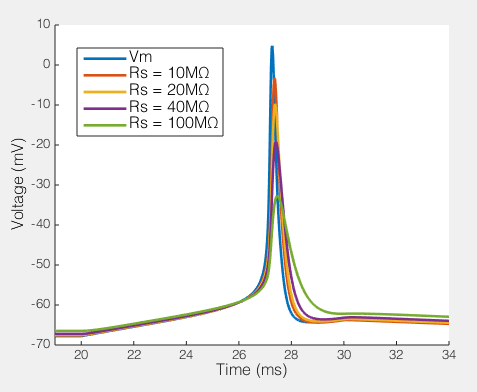
The effect of series resistance on action potentials recorded via a 5pF pipette and an amplifier with 5GΩ input resistance.
Here we see how series resistances effects the ability to record a simple action potential. Clearly, even a relatively modest series resistance start to effect the ability to record action potentials. Likewise, the resting membrane potential is slightly depolarized as Rs gets very high. Potentially the Rp I have included in the model is a bit low, but it’s not massively too low. Moreover, the point remains, Rs, Cp and how much current your amplifier draws creates a filtering system, and if Rs changes, the filter changes. Your amplifiers capacitance neutralization is there to minimize this effect, but it only works if everything is set correctly (and it still only minimizes the effect).
So long story short: In voltage clamp, series resistance prevents your amplifier from charging the membrane capacitor, and in current clamp, series resistance stops your cell from being able to charge the capacitance of your pipette. These things are bad, but what is worse is when it changes over time. So monitor your series resistance constantly throughout your experiment.
Hello Bill,
my name is Riccardo and I am a postdoctoral fellow from Pisa (Italy). I am very grateful to you because your discussion about th series resistance solved most of my doubts about this damned issue. I would like to take advantage from your expertise to ask something about my troubles…
Actually I always have to fight against Rs and often is not easy to me to obtain very low and good values of it…
I know that important tricks are a quite low pipette resistance (as you have written), a good balance in osmolarity between external and intenal solution (with the internal a bit less concentrated than external – 280/290 vs 300), healthy cells, good approach to them and right positive/negative pressure.
Unfortunately what too often happens to me is that I not easily obtain the gigaseal and I have to suck a lot with mouth after releasing the positive pressure, in order to allow resistance to rise. And when I reach the gigaseal it is often hard to break the membrane, and after the fact my Rs is never so low… I noticed that the more easy is the reaching of the gigaseal and breaking of membrane, the higher is the probability to obtain nice Rs.
Unfortunately my pressure system is not very good, because it has an air leak somewhere, and I have to blow with mouth continuously during the cell approach, and I think that this not helps me to obtain nice whole-cells.. What do you think about that?
Thank you very much for your attention, I will appreciate any suggestion!
Riccardo.
Hey Riccardo,
First thing, you’ve got to fix the positive pressure leak. This probably isn’t the cause of the problem, but that will really not be helping (I’ll tell you why soon). Go and beg, borrow or steal some new tubing. Plus, when you’re patching, you’ve got enough to worry about, trying to keep positive pressure by mouth is adding more stress.
It would have been helpful to know what cell type you’re trying to patch. Anyone who has patched a lot of different cell types will tell you that different cells seal at different rates. But given that, as you’ve said, good seals generally = good access (low and stable Rs). When you’re sitting there sucking on the tubing trying to get a seal you are drawing large amounts of the cell (and sometimes processes of other cells) into your pipette. When you finally go whole-cell, all this stuff is still stuck up your pipette (indeed, anyone who has done 2-photon imaging during whole-cell recordings will tell you there is more stuff up your pipette than you realize. Check out these images to see what I mean). So I think if you get good seals, your problem of increasing Rs will be reduced.
At this point, I want to say, can you give me some numbers about your Rs? That is to say, if you start at 10 MOhm, and 20 minutes later, you’re up to 20 MOhm, I would say this is vaguely normally, and sometimes/often you get that. If on the other hand, you start at 20MOhm, and in 3 minutes you’re at 40 MOhm, this is very bad. Also, so long as you’re not trying to voltage clamp sodium currents, for most people, it’s more important to have STABLE Rs, than it has to have LOW Rs. So sometimes actually using a smaller pipette (Rs = 6-7MOhm) can give you more stable access.
So, how do you get a faster former, more stable seal? First, fix that positive pressure leak! If your pressure drops when you’re in the bath or near tissue, this will hamper your ability to form a seal. Also, in my experience, applying too much positive pressure (>300 mbar) can also make you form bad seals. Secondly, are you pipettes and solutions good? I would find someone who is performing patching with no trouble (perhaps on a different cell type), and give them your pipettes and solutions. If they find their seals are bad using your solutions and pipettes, then that tells you the problem. Conversely, use someone elses pipettes and solutions on your cells. If you can seal perfectly, then you know the problem. Finally, are you SURE you cells are healthy? For instance working from very old animals can cause a lot of seal problems. I often tell people to cut cortical slices or cerebellar spices from P16 rat pups. If you can’t patch a layer V pyramidal cell, or a Purkinje cell (assuming you don’t slices their dendrites off), then there is something seriously wrong. (Also, do you have a way of measuring your positive pressure? Purchasing an manometer can be quite expensive (150-300 Euros), but you can make one yourself for not much at all (60 Euros) using something like a SSCSNBN250MBAA5 and an arduino)
But generally speaking, with somatic recordings from healthy cells from animals in the normal age range, the moment you turn off the positive pressure, the resistance should increase to ~>500 MOhm pretty much instantly. If it doesn’t, you’re in trouble. Make that happen, and I think your problems will be fixed. If you’re working with cultured cells, cells from really old or really young animals, then … hard to say.
Hope that helps, but if you want to continue this conversation via email (due to privacy) be my guest.
Hi Bill,
I enjoy your article. This kind of stuff is rarely explained. I’ve got an elementary question. You mention the importance of observing the series resistance during the course of measurements. I’m wondering if it would be possible to measure Rs simultaneously during measurements of synaptic current. Or would it be necessary to pause synaptic current measurement every once in while and to apply pulses in the command voltage for determining Rs?
Thank you so much!
Daisuke
Hi Daisuke,
Sorry about the slow reply. When measuring EVOKED synaptic currents, it is trivial to measure Rs during your recordings. About 100 ms before you evoke the synaptic event, do a -5 mV test pulse. Here is a beautiful old waveform (from a MSDOS based version of winLTP) showing exactly what I mean.
If you have Rs correction/compensation on, then you wont get a nice current response with a capacitive transient, however, you can still monitor changes in your Rs.
If you are doing spontaneous or miniature synaptic events, then you’re in a bit more trouble. I usually patch a cell, waiting around 10 minutes for everything to stabilize, and then start monitoring Rs constantly. I wait for the Rs to get steady, then perform Rs correction/compensation. I then get my 5/10 minute recording of spontaneous events, and monitor Rs again. If it hasn’t changed (and the holding current has stayed largely stable) then I say that recording is good. Generally speaking, an increase in Rs should be paired with the holding current moving towards zero, the holding current itself is a pretty reliable measure of Rs (when you can’t measure it more directly).
Hope that helps.
I really enjoyed the article, thank you very much for sharing knowledge and explain this important subject in a very clear way
Hi Bill,
I’m a master student approaching electrophysiology for the first time. I’m patching cells in current clamp in the midbrain and I always have a really high Rs (around 30 MOhm, sometimes even 50). I tried to reduce pipette resistance, change IC and apply different pressure but there was no improvement. I’m using one year old mice expressing Tdtomato in specific neurons. Do you think this can be a reason for the high Rs? I have to say that the Rs even if high is pretty stable throughout the recording (around 10 minutes) and the shape of AP and firing frequency looks “normal”. Any idea why this happens?
Thank you,
Petra
Hey Petra,
1 year old mice! Rather you than me. Recordings are never going to be as beautiful from such old as they can be from younger mice (though in my experience the recordings can be more long lived). In my books, if your Rs is 3 times the open tip resistance of your electrode, then you’re doing well: i.e. if your pipette is 5 Meg, then a 15 Meg series resistance is good. Obviously, you’re getting much more than this. But as you can read in my post, in current clamp, this isn’t such a big deal. I don’t have any particular tips for you to get better series resistance, especially if they’re starting off high. If the recordings are stable, and less than some threshold, then keep them.
As I imply in the post, to know what theoretical “threshold” you should use for your Rs in current clamp, you need to know the input impedance of your amplifier, which you’re not going to be able to find or measure*. So I would just pick a number, (40 Megs sounds good to me).
*With certain amplifiers, if you pop open the headstage, you can see the op-amp that your signal feeds into, so you could look up the specs, but I suspect the biggest source of current drain isn’t actually the input impedance of that op-amp, but stray capacitances… though don’t quote me on that.
Hi Bill,
A stupid question, how to do calculate the series resistance change after offline analysis? I mean which one are you using to subject ? average series resistance or the lowest series resistance or the highest series resistance or the initial series resistance?
Thank you.
Not a stupid question at all. In order to calculate series resistance (Rs) you’ve got to be in a position to measure it! That means, every once and a while, you’ve got to apply a small voltage step, and measure the size of the current transient. In a perfect world, this is part of your protocol e.g. you apply a 10 mV step 100 ms before you turn on your LED/activate your stimulator/squirt on your drugs. But in some situations (like recording miniature synaptic events) you don’t want to do this. So in that case I would make a measurement ever couple of minutes. You have to have some threshold where you say “if it increases by X% or ever goes about X MegaOhm then I kill the recording”. If you’re not applying voltage steps, you can’t calculate the resistance offline (as far as I know).
Thank you very much for your reply. How do you calculate X% change?
I really appreciate your help.
Just the same way as you would for anything else. If A is the original Rs, and B is the later measured Rs, then the percentage change is 100*(A-B)/A
Sorry, I MAY make things confused. Let me be clear. How do you determine the A? Are you using the average Rs , the maximum or the minimum Rs?
Thanks.
Oh I see. It really depends on how you’re measuring it and what kind of experiment you’re doing. If you measure Rs every 10 minutes, then when you measure it the first time, that one value is your beginning Rs. If you’re measuring it every 5 seconds, then you might as well take an average for the first three readings, but honestly, it shouldn’t really change much over the kind of time course. On the other hand, if you’re measuring Rs by reading off the amplifier Dial/display, then whatever that value is when your experiment starts, that is your starting value.
But giving advice over the internet is hard. When you comment, because I’m the admin, I can see a few details about where in the world you are. And I’ve got to say, there are some EXTREMELY accomplished electrophysiologists near you (or there were last time I was there), so perhaps you should go knock on a few doors. In my experience, when you come looking for advice, people are usually very helpful.
Hi Bill,
Many thanks for your article. I have following questions:
1. I didn’t understand the second ‘take home point’ – “The membrane capacitor and the series resistances sets up a low-pass filter for your command voltage.” Could you please explain what does it mean?
2. I have not understood this statement- “….But this voltage divider is a frequency dependent voltage divider, because capacitors let more current through when the voltage across them changes rapidly. ” I would like to know which frequency you are talking about. This may not be a good question, but I really didn’t understand.
thank you,
rick
So I’m not 100% sure what you’re stuck on Rick, so I’ll go through and explain each term.
The “membrane capacitor” is what we use to describe the fundamental electrical behaviour of a cell, specifically, that if you put a constant current into it, the voltage across it begins to grow linearly.
The “series resistance” is the effect caused by the fact that your preamplifier is not plugged directly into the cell. This means that as you pass current into the cell, a voltage proportional to that current is generated between the preamplifier and the inside of the cell.
A “low-pass filter” is a conceptual description of any system that removes fast changing signals, and allows slow changing signals to pass through.
Your “command voltage” is the voltage you wish to impose over the membrane of the cell.
So the second take home point is saying that because of the membrane capacitor (that requires current to pass into it to change it’s voltage) and the series resistor (which creates a voltage across itself when you pass current through it) prevent you from being able to change the membrane potential rapidly (i.e. they act like a low pass filter for your command voltage). This is because at the microsecond that you try to change the voltage a current will flow from your preamplifier into the cell. At that microsecond, the voltage over the membrane capacitor (Vc) will only have changed a tiny bit, however, the voltage over the series resistor (Vsr) will be non-zero (as the voltage over the series resistor is proportional to current). Thus you preamplifier will “see” that the voltage is Vc + Vsr, and hence it will pass less current than if the preamplifer knew the “truth”, which is that the voltage over the cell is only Vc.
Your second question: What frequency am I talking about? The frequency at which the voltage across the voltage divider is changing. Have a look at this page and it might make more sense.
Hi Bill,
Many thanks for your reply. I read your article on voltage dividers. Interactive demos helped me a lot!
So, if I have understood the concept correctly, series resistance with membrane capacitance give rise to low pass filter as a result of which fast changing signals (such as rapid voltage changes that occur during electrophysiology experiments) go through the membrane capacitor and are removed, which is not good from experimenter’s point of view, right? (by the way, I still haven’t clear about how actually this ‘removal’ across the membrane occurs physically)
I wonder if (1) pipette capacitance also contributes to low pass filtering and (2) Is noise always a high frequency signal (in electrophysiology experiments).
Best,
Rick
It sounds like you’re getting the concept.
” I still haven’t clear about how actually this ‘removal’ across the membrane occurs physically”
The description below ended up a bit long winded. Let’s try a briefer one. A resistor develops a voltage across it as soon as current is passed through it. A capacitor on the other hand integrates the charge that is stored on it to develop a voltage, i.e. it’s voltage grows linearly with a constant current. This is why it is said that capacitors behave like a low resistance for fast changing voltages: the capacitor doesn’t have time to develop a voltage across it if the current being driven into it is alternating rapidly.
Well there are a lot of different ways to explain how capacitors work, but I find that “hydraulic” analogy is a good place to start. In this analogy, charge is equivalent to water. This makes the flow of current equivalent to the flow of water. A voltage difference is the same as a pressure difference, i.e. if two pipes are connected, and there is a pressure difference between then, then water flows from the pipe of high pressure, to the pipe of low pressure (just like how electrical current moves from wires of high voltage to low voltage). In this analogy, resistors are like a section of pipe with a small opening: if water flows through a pipe with a small opening, you get reduced flow, and a big pressure difference from one side of the opening to the other. A capacitor is like a rubber membrane stretched over a pipe. When current starts to flow down the pipe, the membrane stretches easily, so you don’t get much of a pressure drop over the membrane, however, as current continues flow the membrane stretches more and more and a pressure differences begins to develop i.e. if you provide constant current into a capacitor, the voltage over it grows linearly. On the other hand, Imagine we have our membrane stretched over a pipe with a small opening (i.e. a resistor and capacitor in series) and we apply a lot of pressure to the other end of the pipe. Water will begin to flow down the pipe, and begin to inflate the rubber membrane. Because the rubber membrane is only just being stretched a little bit, there is almost no pressure difference from one side of the membrane to the other, however, because water is flowing, there is a big pressure difference from one side of the pipe to the other. However, as water continues to flow, the rubber membrane begins to expand and resist the flow. Now we are developing a pressure difference over the membrane, and because the flow is being reduced, we are getting less pressure drop over the pipe. Eventually all of the pressure we applied forms over the membrane, and we have no flow of water at all, and there is no pressure difference over the pipe at all. This situation is like our resistor-capacitor low-pass filter: When we try to impose voltage over the capacitor we have a resistor in the way which slows the rate of current flow into the capacitor. However, as the capacitor begins to charge, this reduces the voltage difference over the resistor, meaning less current flows meaning the voltage over the capacitor grows more slowly. After a very long time, the voltage over the capacitor is essentially equal to the applied voltage, there is no voltage over the resistor and no current flow at all.
Thank you very much Bill for your quick reply. I understood it! Could you please also comment on the last two points in my post?
“I wonder if (1) pipette capacitance also contributes to low pass filtering”
See the article, it does in current clamp, but in practice, not in voltage clamp (in general, we rule out pipette capacitance (Cp) in voltage clamp as a filter, as we say that Cp is in series with the command voltage, i.e the is no resistance between the wire in your pipette and Cp. This is not strictly speaking true, as lots of Cp is made up by the very tip of your pipette, and there is non-negligible resistance between the tip of your pipette and the wire. However, the resistance is relatively low, and that capacitance is relatively low, so it certainly is not a large filter. i.e. in practice, in voltage we don’t tend to worry about it. People who do voltage clamp recordings of single channel behaviour get concerned about how Cp makes noise, but that is a different matter).
“(2) Is noise always a high frequency signal (in electrophysiology experiments).”
No. In general, noise follows a “1/f” rule, meaning that the power in the a frequency bad is inversely proportional to the frequency. There are lots of ways to justify this, but the simpliest is that there is more energy in high frequency vibrations than in low frequency ones (move your arm up and down at 1 Hz… no problem. Now do it at 10 Hz: you’re exhausted). Hence unless you have an infinite energy supply, there must be lower power at higher frequencies. Obviously this isn’t a hard and fast rule, as you often get peaks in the frequency domain at 50/60Hz due to the mains power, and then again at the 10-100 kHz band due to switching power supplies and then various other peaks due to other sources, but all of this is nested in a 1/f power spectrum. Just off the top of my head, see this
Also, some scientists get a bit worked up with my usage of “noise”. Some believe that “noise” must be a random processes, and hence the 50Hz or 40kHz signal from mains power/switching power supplies isn’t noise, but “hum” or interference. Those people are what everyone else calls “pedantic”. Moreover, a word can have more than one meaning, in this case, everything that isn’t signal is noise. This isn’t aimed at you Rick, this is just in case one of those pedants ends up reading this.
For what it’s worth, it seems to me that having a read of some of the chapters in “Single Channel Recording” could help you out.
Thank you very much Bill for your reply. Now, it’s more clear to me. I will read the book you suggested.
I appreciate your help.
Thank you very much for your post; it’s really great and very well explained! Well done for your effort! However, perhaps I’m missing something and I’m a bit confused. So, if I give a voltage pulse to estimate changes in series resistance, don’t I measure the sum of both series resistance and membrane resistance? If I observe any changes in the recorded amplitude, why should I interpret this as changes in series resistance?
Many thank in advance
I’m having a bit of difficulty understanding what exactly is the meaning/interpretation of a change in series resistance. If I understand correctly, the series resistance (Rs) includes the membrane resistance (Rm), too. So, in principle changes in Rm could contribute to changes in Rs. I haven’t found any sources discussing about this, while at the same time, there are a lot of articles published that report rejecting cells due to changes in Rs. I was wondering if I’m missing something there. Perhaps you could help me understand.
Thank you very much in advance.
Hi Harry,
There are definitely a few things we need to clear up. One of which I am going to try to make a full blog post about (how to actually measure Rs).
However, I’ve just become a father (literally about 5 hours ago) so I’m not quite in the position to write a proper response.
I’ll try to remember to get back to you, but if you haven’t heard back by the middle of next week, post a quick reminder.
Hey Harry,
So look at the first figure, the circuit representation. What he have is the series resistance (Rs) in series with the membrane capacitor (Cm) and the membrane resistance (Rm), which are in parallel. At *steady state* (i.e. time equals infinity, if the applied voltage never changes) your understanding of what is happening is exactly correct: the apparent resistance measured at the pipette is exactly equal to the sum of Rm and Rs. However, this is very different if the applied voltage (Vcmd) is changing. Roughly speaking, we can use this equation for the membrane capacitor (it’s not exactly correct because of Rs, but it’s good enough for now)
I = Cm * dVcmd / dt
Where I is the current through Cm. We normally thing of resistance in terms of Ohms law, where we say I = V/R, which means that the current through a *resistor* is high when the resistance is low. With that capacitor equation in mind, which says that the current through a *capacitor* is high when the rate of voltage change is high, you can see why it is often said that “a capacitor behaves like very low resistance when the voltage is changing rapidly”.
So if Cm behaves like a very small resistance (approaching zero) when the voltage is changing rapidly, what happens to the circuit as a whole? Well we can see that Rm in parralel with Cm (which is now a 0 ohm resistor) can be treated as a zero ohm resistor. Then Rs in series in series with our imagined zero ohm resistor can be treated as a single resistor with a value equal to Rs. So, to say that again, if the voltage is changing rapidly, then the whole circuit just becomes Rs. (This approximation only works when Rs is small relative to Rm).
So how do we make the voltage change rapidly? Well we applied a voltage step/square step: that’s the most rapid voltage change we can produce!. But of course the voltage is only changing rapidly right at the beginning of the step (after that it is not changing at all). So right at the beginning of a voltage step, you can look at the magnitude of the current transient (which looks like this) and simply apply ohms law, Rs = V/I, where V is the magnitude of the voltage step, and I is the magnitude of the current transient.
There are a few caveats (like as I said, it only works were Rs is much much less than Rm). But I think I’ve given you enough to think about for now.
Hi Bill,
In response to “Also, so long as you’re not trying to voltage clamp sodium currents, for most people, it’s more important to have STABLE Rs, than it has to have LOW Rs.” Why is it more important to have a low Rs with sodium current recordings? Is it because the Na current can be very large?
Best wishes,
Molly
Hi Molly,
Na Currents are tricky because they’re a) fast, b) often large, and c) create a positive feedback loop on your voltage clamp error.
a) As I’ve said, in voltage clamp, Rs (together with membrane capacitance) sets up a low pass filter for your command voltage. Sodium currents can have rise times as quick as 100 microseconds. Which means 10 kHz. Even with a trivial Cm of 10 pF and a tiny Rs of 2 MOhm, the cut off frequency of your filter is 8 kHz. So you’re really only just clamping fast enough to capture the rise time of your current.
b) Sodium currents can be large, and your steady state voltage error is equal to I_clamp * Rs… So if you have a 1 nA current, and a 2 MOhm Rs, you have a 2 mV voltage error (at steady state, which you probably wont reach, but lets ignore that)… But if you have a 5MOhm Rs and a 5 nA current, now you have a 25 mV voltage error. That is bad.
c) Sodium current depolarizes you cell, which activates more sodium channels, leading to a bigger current, which worsens your voltage clamp, which leads to more current etc etc etc… If it was a potassium current, bad voltage clamp dampens excitability. It’s still not ideal but you don’t get a run-away loss of voltage clamp. Thankfully, it is very obvious (once you know what to look for) when you see recordings like this. Have a look at this paper and compare figure 7A to 7B. You see how in the activation curve in 7A, the sodium current instantly jumps to maximum size, then slowly gets smaller? This is run-away loss of voltage clamp, also called an action current. Proper voltage clamp should produce a steady activation of sodium currents with around 20 mV between when the current starts to be active and when the current reaches maximum. You can find quite a few published papers where there is a 5 mV between the current being activated and the current reaching max. You know these people don’t have voltage clamp.
Hi Bill,
Thanks so much for your thorough explanations about this topic. They have helped me understand my amplifier on a much deeper level. I have a question about the low pass filter created by the series resistance and the membrane capacitance, specifically when working in voltage clamp mode. I believe I know the answer, but I would like to be certain.
Does this only filter voltage, or is current filtered as well?
Thanks for your help,
Dan
Hi Dan,
> Does this only filter voltage, or is current filtered as well?
Yes, both voltage and current are filtered, both the exact same time constant roughly equal to Cm * Rs. Look at figure 3 and 4 (i.e. the current and voltage in response to a synaptic event). You see that some voltage is unclamped, especially the fast components. I really should have had a figure showing the voltage and current in response to a typical square step. But if you look in the Axon Guide, look for figure 3-14. It shows the important stuff.
Hi Bill,
It turns out I did not know the answer, so I’m glad I asked. I’m hoping that now you can help me clear up some confusion and connect the dots.
Does this filtering just apply to the response to the initial voltage jump, or does it continue as the membrane voltage comes to steady state? For instance, I have a 4-pole bessel filter with a cutoff frequency of 5 kHz, but if my time constant is 60 us then the cutoff frequency of the RsCm low pass filter will be 1/(2*pi*60) = 2.65 kHz. This means I wouldn’t see fast events that I thought I should be able to see based on my sampling rate (100 kHz) and my filter. Am I thinking about this correctly, or is this filtering actually controlled by the CpRs cutoff frequency, as in current clamp?
Also, I thought that the reason the measured current was less than it should be in figure 3 was because of the voltage error created by the Rs. If the current is 100 pA, and Rs is 40 MOhms, then the voltage error at the peak of the current is 0.1*40 = 4 mV. I know when I’m evoking current in sodium channels, the holding voltage error will skew my G/V curves, but maybe I’m misunderstanding this graph. You say in parentheses “the synaptic event is current based, rather than conductance, so it is the same no matter how bad the voltage clamp is”, but if you have a voltage error in your command potential, then the driving force on the ion would be different. Maybe that’s not enough to account for the difference, though.
Thanks for your help and all your patient and thorough explanations.
Hi Again Dan,
So we’re talking voltage clamp correct? So if the filter on your amplifier is set to 5 kHz, then that means any current you record faster than 5 kHz is basically gone (and in reality, you’re filtering currents down to about 1.5 kHz, see my post on filtering). But lets look at what you can actually record. If you’re saying that RsCm = 60 us, then that sets up a 1-pole filter of 2.7 kHz for both the transmembrane voltage you are applying, and transmembrane current you are trying to record. So yes, your 100 kHz sampling rate is way over kill. You don’t want to actually use the Nyquist theory on your “practical” data rate (e.g. sampling at 2.7 kHz * 2 = 5.4 kHz, because you will still be sampling noise at 5 kHz or so. So I would use a bare minimum of 10 kHz… and probably use 20/25 kHz just to get nice waveforms). But yes, you would absolutely be kidding yourself if you thought that you transmembrane currents were accurate up to 100 kHz. CpRs is another filter, but in the scheme of voltage clamp, it is usually insignificant, and Cp is more likely to cause problems due to leak subtraction, or noise (though there are edge cases where Cp*Rs is a significant filter).
> Does this filtering just apply to the response to the initial voltage jump, or does it continue as the membrane voltage comes to steady state?
The “filtering” (as in, altering a signal based on it’s frequency) only applies to the initial jump. However, as I see you know from what you say later on, there is a voltage error caused by I-clamp * Rs. The combination of the filtering and the voltage error is shown in the transfer functions in figure 2.
> Also, I thought that the reason the measured current was less than it should be in figure 3 was because of the voltage error created by the Rs. If the current is 100 pA, and Rs is 40 MOhms, then the voltage error at the peak of the current is 0.1*40 = 4 mV.
I don’t think that would be the best way to think about it. As I say in parenthesis, the simulated synaptic event is current based, so there is no driving force. Think of it like another pipette in current clamp mode, forcing a 100 pA-peak synaptic event into the cell. It doesn’t not matter what potential the cell gets to: it will always inject 100 pA. I always like to think about voltage clamp in terms of a voltage divider: one resister is made up of Rs, and the other is made up of Rm and Cm. When we apply a voltage, that voltage falls across Rs (voltage error) and Rm || Cm. When that voltage is changing rapidly, Rm || Cm appears as a very low impedance, and hence most of the applied voltage lands over Rs. But more importantly, as Rm || Cm appears as a low impedance, most current flow will over Rm || Cm, and hence you will record less current.
In reality, there are lots of ways to think about this. Some ways work better for some people than others, so have a think about it from lots of different angles (i.e. think about it from the point of view of Vcmd… think about it from the point of view of Vm and think about it if we injected current directly into the cell, i.e. at the junction of Rs and Rm || Cm.
But Let me know if you’ve got any more questions or if I misunderstood you.
Dear Bill,
Thank you for this invaluable resource. I am looking to model my own series resistance/pipette capacitance and was wondering what code you use to do this? Is it something you wrote yourself/is it open access? I found some useful looking links on the NEURON forum but they were broken due to the age of the posts.
Best wishes,
Charlotte
I’ll respond via email, but quickly just in case anyone else reads this: the frequency-amplitude graphs are just from the equations that govern RC circuits. The waveforms were generated in NEURON. Though it is pretty simple to numerically simulate the behaviour of a single compartment under current and voltage clamp.
Hi Bill,
Thank you so much for all your educational posts. As a student learning to patch clamp, these have been very helpful. I have a question about the voltage divider equation. Would you be able to show me how you have derived it? I only have a basic knowledge of physics and after studying your scheme for hours, I figured I would better ask for your help… Thank you so much in advance!
Hi Laura,
Because everything in the circuit is linear (i.e. if you double the voltage, you double the current), you can use a trick called “superposition”, don’t worry, it’s simpler than it sounds.
You split the circuit in into simplified versions, where there is only one voltage source. You convert any other voltage source to a wire. Then you solve for your value of interest in the simplified versions.
Then you just add up the simplified versions. Hopefully an image of how I did it will show up below:
Hi Bill,
I redid this exercise and yes, this cleared it up for me! Thank you for your quick response!!