In electronic design, the voltage divider is probably the most fundamental circuit motif. You would be hard pressed to find single circuit that doesn’t have one. But more importantly, it is a deeply useful concept for explaining the physiology of excitable cells, and for understanding the nature of electrophysiological techniques. I’ve talked about voltage dividers in several of my posts, but one of my readers said I should explain what they are so that’s what I’m going to do now.
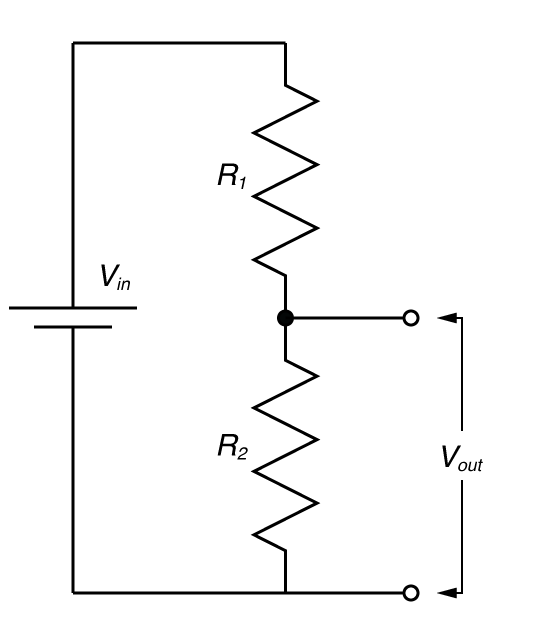
The diagram to the right shows the fundamental form of the voltage divider. We have a supplied voltage (Vin) which is applied across two resistors, then we access the voltage just across one of the resistors (Vout). Vin has now been split (divided) across these two resistors. Why do we do this? Well in circuit design, this might be because some part of out circuit might need a lower voltage to work, and it can be more sensible to make a voltage divider, rather than put in another battery (or voltage regulator) to produce this voltage. What is the value of Vout? Well some very simple math should tell us.
The total resistance of the circuit is just R1 + R2 (resistors in series add). So the current that flows through R1 and R2 can be calculate by Ohms law:
The voltage over R2 = Vout, and again, by Ohms law
So you can either remember that formula, or work it out on the fly. What you should see is that as R2 becomes large relative to R1, then Vout = Vin and as R2 becomes small relative to R1, Vout approaches 0. But perhaps a demonstration might help give you a more intuitive feel, so have a play around with this.
So hopefully you’ve got an idea of how voltage dividers work: If R2 has a low resistance then Vout approaches zero, and if R2 has a high resistance, Vout approaches Vin. So how can we, as electrophysiologists use this? Well why don’t we make Vin some signal we want to record but it’s mixed with some noise we don’t, and wouldn’t it be great if we had a special resistor that would have a low resistance when signals we didn’t want were coming through, and a high resistance at all other times. Let’s say we don’t want high frequency signals; only low frequency signals. So we need a special resistor that has a high resistance to low frequencies, and a low resistance to high frequencies. Well we do have such a ‘resistor’, and it’s called a capacitor! When the voltage across a capacitor is changing rapidly, it draws lots of current (i.e. it behaves like a low resistance) while when the voltage is changing very slowly, it draws almost no current (high resistance). So if we replace R2 with a capacitor we create a low-pass filter. By choosing the values of R1 and the capacitor, we can decide the cut off frequency (Fc) which is roughly the point where the signals start being significantly attenuated, with the equation
I’ve made an interactive demo, to try to give you a feel for how it works.
By swapping the positions of resistor and the capacitor, you can make a high-pass filter, and theoretically, you can also use an inductor (which presents a high resistance to rapidly changing voltages), though you probably wont do this in practice. Furthermore, in practice, filters are made out of many more repetitions of this kind of circuit, and with integrated circuits called op-amps, to make them perform better, but fundamentally they behave in the same fashion: they are frequency dependent voltage dividers. As an electrophysiologist, a lot of the limitations of your favorite recording technique can understood by looking for a voltage divider. You can consider how voltages spread from the soma to the dendrite by using the voltage divider as a metaphor. Indeed, I doubt there is a bioelectrical signal that you can’t get some insight into by looking at it through the lens of the voltage divider.
Thanks for the useful educational post. I really enjoyed the simulation things that visualizes the relationship between voltage drop and resistance. I thought to share an additional tool that might help your readers for calculating voltage divided across the resistors:
Thanks & Regards
Hi, the illustration is simple, nice and good for educating kids.