Even though we are now in the era of optogenetics, electrical stimulation of excitable tissues is still common place in the lab. However, despite how common they are, I see that a lot of people don’t fully understand why they using some fancy expensive box to deliver the stimulus, rather than just, say, using the DAC output of your digitizer. The actual physics of why passing current through your tissue excites neurons/muscles is a bit more complex than you might think, but that’s not what I’m going to talk about. I’m going to talk about what a stimulus isolator is, and why we use them.
Stimulus Isolators can be split up it two ways: the first way is battery powered versus mains powered, and the second way is constant current versus constant voltage. For the discussion today, it makes no difference. In both constant voltage and constant current stimulators, a voltage drives current between the two output terminals of the stimulator. And mains powered stimulus isolators try their very best to approximate battery powered stimulus isolators by running the AC voltages from the mains through some kind of transformer, which effectively “isolates” the stimulus isolator from earth. What do I mean what I say “isolates”? I mean that if a power source is isolated from earth, then the output of that power source cannot be measured relative to earth, as no current wants to flow from the power output to earth. Still confused? Let’s look at Fig. 1.
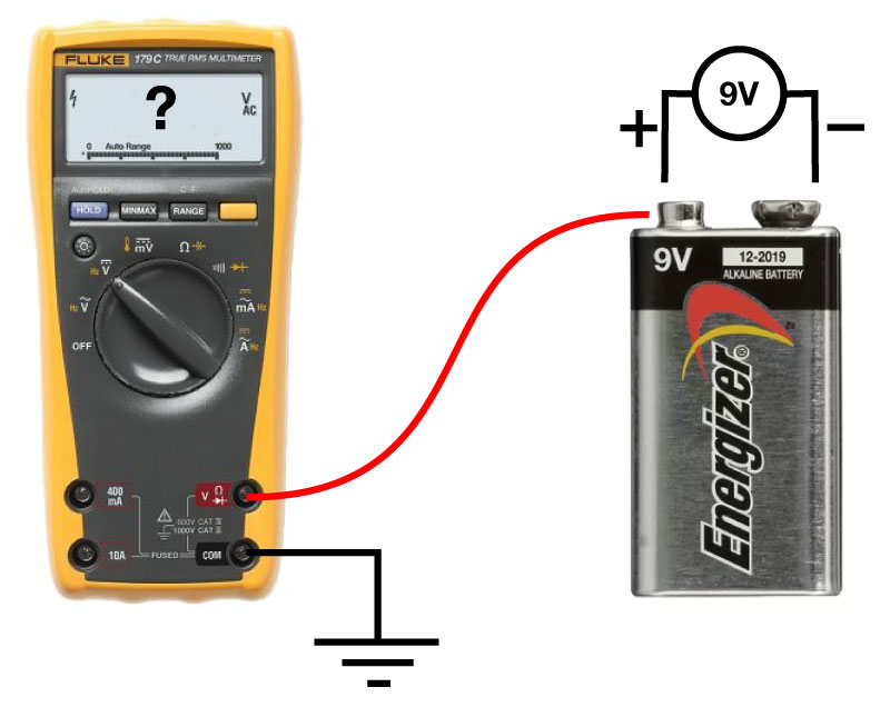
Fig 1. What voltage does the multimeter record?
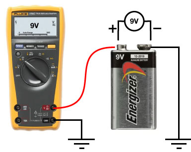
By connecting the negative terminal to ground, now we can measure the voltage over the battery.
So what does this have to do with stimulus isolators? Well if we replace the battery with a stimulus isolator, and the multimeter with our electrode connected to a preamplifier, we have a typical electrophysiology set up. If our stimulator is not isolated from ground, then the voltage it creates will be directly sensed by our preamplifier. How does this work? Well have a look at Fig 3.
Fig 3. shows us a non-isolated stimulator. I’ve drawn it’s power supply as a battery, but it could as well be a voltage output from a DAC or any other non-isolated voltage. Our recording electrode is sampling the voltage at VRecord, which is the same place as the two electrodes of our bipolar stimulating electrode (yes, there will be some resistance between all of these, but they don’t really matter in order to get a conceptual understanding).
Fig 3. Non-isolator stimulator. See text for details.
Fig 4. An Isolated Stimulator. See text for details.
Now you may be saying “Hang on there, I’ve used a stimulus isolator before, and I still see a stimulus artifact”, and of course, you do. This is because while a good stimulus isolator is essentially completely isolated from ground, resistively speaking, it still has some capacitive coupling to ground, usually on the order of 1-10’s of pF. So this is like putting a capacitor between the battery and ground in Fig 3. What this means is that rapidly changing voltages caused by your stimulator still allow some current to flow through RGround, creating a small stimulus artifact, but the smaller this capacitive coupling is, this smaller and briefer the artifact will be.
So what does this mean? It means don’t ground either of the output pins of your stimulator or you will undo all the engineering that has gone into the design of your stimulator! It means don’t let the leads which run to your stimulator run all over your rig (which increases the capacitive coupling to ground). While I’ve found wrapping your stimulator leads in a grounded shield (or using coaxial cables with a grounded shield) is a good way to remove high frequency noise introduced by the stimulator (or more the leads attached to the stimulator acting like antennas), it also can increase the capacitive coupling to ground, so you get a bigger artifact.
There is another benefit of using stimulus isolators: safety. Specifically, if you were to hold onto the positive output of a non-isolated 100V stimulator, it wouldn’t be fun, as current could flow through you, into ground, and from ground, back to the stimulator. However, if this stimulator was isolated this couldn’t happen, as there is no return path from ground to the stimulator. It’s basically the inverse of why birds can sit on overhead cables carrying mains electricity: the bird is isolated from ground, while the power isn’t, in our case however, it is the power which is isolated from ground, while you aren’t. In practice, if your are an in vitro scientist, this is a pretty theoretically benefit, but if you are using stimulators in a clinical setting to excite nerves or muscles, this is very important, as the last thing you want is current to flow through your patients heart to ground: you only want the current to flow between the two poles of your stimulating electrodes and into the muscle/nerve of choice.
Nice article. The forgotten dark arts…
I usually try to explain the utility of isolation by the need for a full current loop (which can’t cross the isolation barrier).
I can add a few thoughts/comments:
– Current across the bath electrode is a problem in voltage clamp because the voltage artefact alters the clamp voltage of the cell; in current clamp it is simply added to the recorded voltage, so is only ugly while it flows
– Capacitive coupling of high-voltage transients into the electrode (through air) can be a big problem, exciting your cell; shielding the cables definitely helps here. To give some idea of the sensitivity, we routinely detect action potential signals between electrodes by this mechanism; stimulating voltages can be hundreds of times greater and rise much more quickly (capacitive coupling current is proportional to dV/dt).
– Balancing the + and – stimulating voltages tends to cancel the transient. This happens naturally for bipolar electrodes, but doing so for a monopolar stim would require a sophisticated circuit.
– Also good to run cables together to reduce loop areas and improve cancellation.
– Stimulation in current is best for reproducibility, but causes longer artefacts (electrode and cable capacitance must be discharged through the stimulating electrode) and this is made worse by cable capacitance to ground (shields); much less of a problem in voltage.
– AC isolators still have a capacitance to ground through the transformer; these capacitances can be made quite small if designed with this in mind, but given the lack of information in typical stimulator specifications, the designers probably didn’t think of that.
– The switching circuits providing AC-isolated power nearly always generate difficult noise; very careful design seems to be required to avoid that problem. So far I’ve not found an AC-isolated model without noticeable noise, but I’ve been told Digitimer managed.
– One can avoid an isolator by using a virtual ground (clamping the bath to ground, whatever stimulator current flows); this removes the need for isolation and therefore for noisy AC isolators (I hate batteries).
Thanks for your detailed response Boris. 100% agree with everything you say. Though, I must admit, while I have read about virtual grounds, I’ve never used one, and don’t really understand the theory beyond “you are clamping the bath to ground”. Is it something that be done with modern amplifiers, or did it go out with the axopatch?
I think virtual grounds are used with oocyte recordings, on account of the very large currents that flow. But it’s a pretty straight forward (external) opamp circuit. Opamp output drives bath voltage (connected to the inverting input via one bath electrode) to some external reference voltage (connected to the noninverting input via another bath electrode; I used the surrounding stage as the reference). You can then just stimulate using a nonisolated voltage referenced to the stage; the virtual ground ensures that the bath voltage doesn’t change (much). It might be necessary to put a feedback resistor and capacitor across the opamp for stability, but I seem to remember that it wasn’t actually.
Seems like stimulus isolators would be fairly easy to build, rather than buying them for $1000 a piece. Why are there no DIY plans online?
Hi John,
There are a few plans out there, but it’s not quite as easy as you think. While making a stimulator that could deliver a fixed constant voltage of a fixed duration would be relatively easy, one that can produce a variable constant-current with variable duration in response to a TTL pulse starts to get quite tricky. You probably want to get it all analog and avoid and oscillating voltage converters to avoid an introduction of noise.
There is this famous circuit https://people.ece.cornell.edu/land/PROJECTS/SIU/index.html
It DOES use a oscillating voltage converter, which I think is a bad design call. They say it works. Personally, I’d just stack 10 9V batteries to get the voltage.
I am also aware of this:
“An optically coupled power stimulus isolation unit with high voltage and fast rise time output” again, it uses a big stack of DC-DC converters to get a rather terrifyingly high compliant voltage (200 V!).
But still, I agree, a simple constant voltage stimulus isolator should not be terribly hard to build. It’s in my stack of thoughts, but if I had the time I’d be building an open source current clamp amplifier.