I’ve talked before about the problems series resistance [i.e. the resistance formed by the tip of your electrode and the gunk in it] poses when you’re performing whole-cell voltage clamp recordings. Simply put, it limits your ability to hold the cell at the voltages you want to, because every time you pass current, some voltage forms over the series resistance and you’re amplifier can’t tell the difference between the voltage over the membrane and the voltage over your series resistor. It also limits your temporal accuracy, as it helps to set up up a low pass filter for your command potential. Thankfully, because the problem is essentially inescapable during whole-cell voltage clamp, essentially all voltage clamp amplifiers come with series resistance compensation: an electronic procedure where the amplifier estimates how much of a problem your series resistance will be, and works to minimize it. However, in order for that circuitry to work, your amplifier needs to know the whole-cell capacitance of the cell you’re recording from (Cm) and how much series resistance (Rs) you’re up against. Typically your set these values while looking at the current response to a test pulse. However, outside of a few select examples, this process of telling the amplifier what Cm and Rs is (know as “correcting for whole-cell parameters” or “capacitance compensation”) isn’t actually trivial. Let’s have a look at why this is, and how we should be doing it in real cells
Near the start of any instructional manual on voltage clamp, there is a section describing how when you first break into a cell you correct for whole cell capacitance and series resistance, turning the capacitive transient you see in response to a voltage step into a smoothly rising curve (Fig 1).
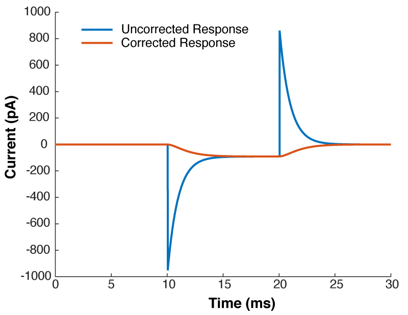
This doesn’t do anything to improve your voltage clamp, but it does provide a little electrical help to the amplifier (See Note 1). More importantly however, it informs your amplifier what Rs and Cm are so that the series resistance compensation circuit can work.
Because of the fact that the Rs and Cm values you put into your amplifier are used for series resistance compensation, their exact values matter: If you over-estimate Rs, the Vm of the cell will be pushed further from the resting membrane potential than you expect. If you over estimate Cm, the voltage of the cell will oscillate before settling at a final value.
Despite the importance of setting the Rs and Cm values on your amplifier, I’ve never seen a guide on how to actually do it. If you patch HEK-293 cells, or N1E-115s, it’s simple: either slowly increase Rs and Cm together, and you will eventually zero in on the correct values. Or, slightly more scientifically, estimate Rs by dividing the size of the voltage step you are applying by the peak amplitude of the capacitive transient, dial that in and then increase Cm until you are left with a smooth rising curve like that shown in Fig 1. (you’ll probably need to do some slight adjustment of Rs to get it perfect). However, in neuron with dendrites, things are not quite so simple.
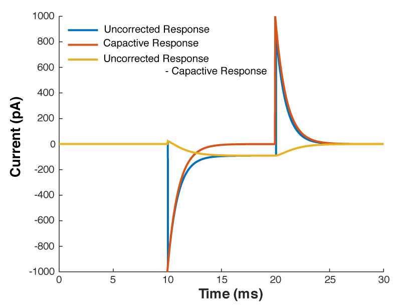
You see, when you set the whole-cell parameters, all the amplifier does is subtract off the current needed to charge a capacitor through a resistor with values equal to the Cm and Rs values you have entered on the amplifier. Want to see what I mean?
The current through a capacitor and resistor in series is described by this equation:
$latex I = \frac{ V_{cmd} }{R_{s}}e^{\frac{-t}{R_{s}C_{m}}} &s=3$
So we can calculate that current, and mathematically subtract it from the response to out test pulse, and we should end up with what we saw in figure 1. Look at figure 2 below, that’s exactly what I’ve done. The blue line is the raw trace, the orange line was calculated with the equation above, and when I take the difference of those two lines I end up with the yellow curve, which looks almost exactly like what we saw in figure 1.
But what all of this means is that if your cell isn’t made up of a capacitor with the value you have entered, and/or that capacitor isn’t being charged through a resistor of the size you have entered, then you’re going to be in trouble. And you’re nearly always going to be in trouble if you’re patching a real neuron as they can never be explained by a single capacitor. And that means that no matter how you set Rs and Cm on your amplifier, you can never get the current to look like what you see in Fig 1. Instead, it looks like Fig 3.
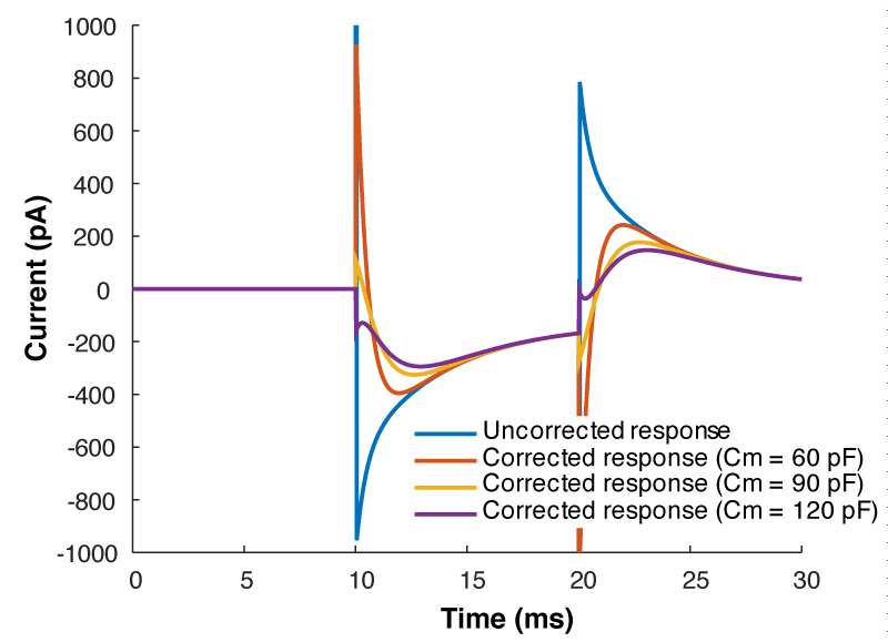
What is going on here? Why can’t you get a textbook response in your current when you patch a neuron? Well as I said above, when you dial in your whole cell parameters, you are just subtracting off the response of a capacitor being charged through a resistor. However, a real cell with dendrites can’t be described by a single capacitor, it has dendritic compartments with capacitance, and the dendritic capacitance doesn’t just add to the somatic capacitance because the dendrite is hidden behind the resistance of the cytoplasm down the dendrite (which acts exactly like another series resistor). Because of that, it is impossible to get the waveform to look like figure 1. So how should the waveform appear to let you know you have correctly dialed in the whole cell parameters?
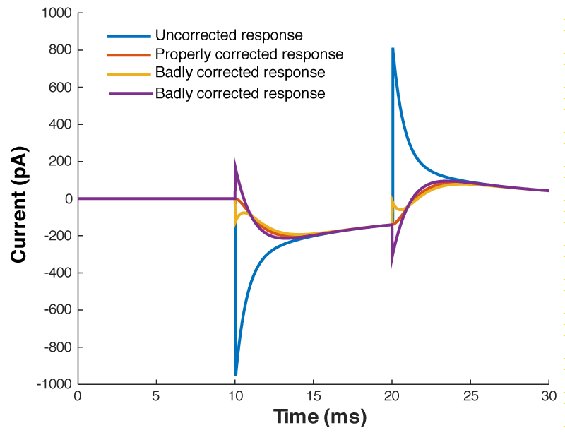
Figure 4 shows a properly corrected response along with two bad examples. I’ve seen people incorrectly dial in Cm and Rs in a futile attempt to get the waveform to look like a textbook response, and it usually looks like the purple and yellow traces. People think that they want a fast rising response, so over set Rs to get a squarish looking step. Yes, you do want a fast rising response, but you achieve this by ACTUALLY lowering Rs, not by mis-setting Rs on the amplifier. I’ve also seen people underset Cm in order to make the response look more square. This can be especially easy to do if you have aggressive low pass filtering (e.g. 1 kHz) as it will clip off where the current goes in the wrong direction (i.e. the positive going current at the start of the step). What you’re looking for is a smooth rise from the holding current when your test pulse starts, and you shouldn’t worry yourself about the departure from squareness as there is nothing you can do about it. The approach of calculating Rs from the peak size of the capacative transient, and then dialing in Cm until the transient disappears is still the best approach.
So do you want to see what this looks like in real life? [All the above graphs were generated in NEURON]. Thankfully I made some recordings where I made dual whole-cell recordings from a single soma. One electrode was in voltage clamp and the other was in current clamp. This allows the electrode in current clamp to measure exactly how our voltage clamp was performing. In the below waveforms, the current trace from the electrode in voltage clamp is on top (Ihold) and the membrane potential is shown on the bottom. The voltage clamp is attempting to make a voltage step from -70 mV to – 80mV. I have turned on 70% series resistance compensation which will then demonstrate the effect of incorrectly applying whole-cell correction.
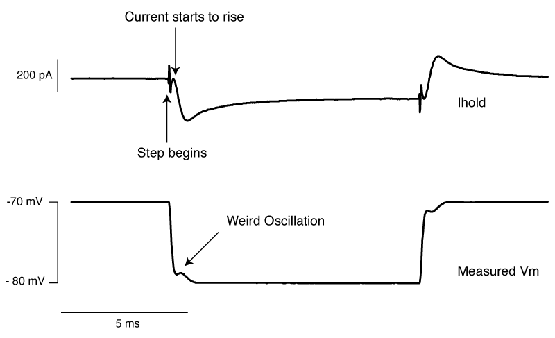
The above shows us a very common mistake. Everything about the current response looks right, apart from one crucial detail: the current starts to rise several 100 microseconds after the step truly begins. This means that the whole cell capacitance is over set, and it leads to a little oscillation in the voltage response.
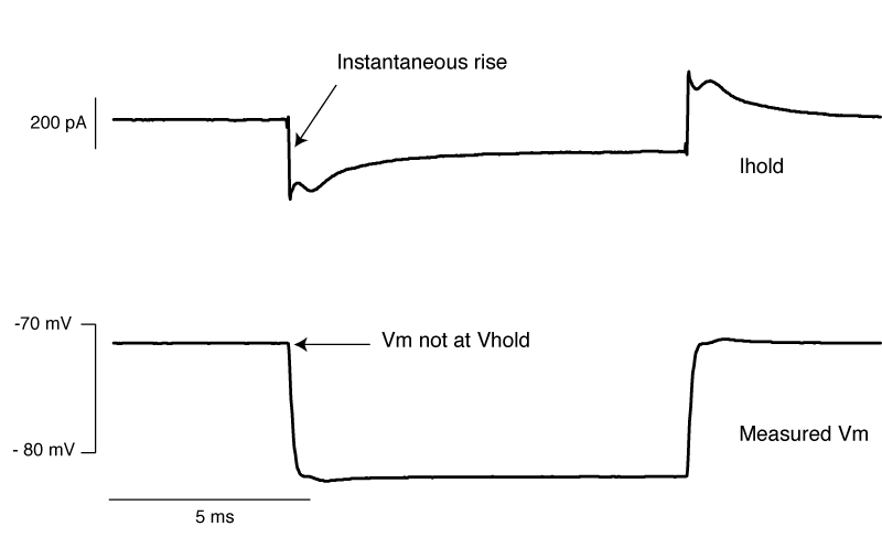
The above is what it looks like when you overset Rs. The only time I’ve seen this in the wild is when the true series resistance into a cell randomly drops without anyone noticing. . You can see the current response shows an instantaneous rise. By oversetting Rs, the series resistance compensation is over doing things, and hence despite met telling the amplifier to clamp the cell at -70 mV, we’re actually at about -72 mV. Likewise, the step amplitude is larger than -10 mV. A 1 mV error is really nothing to worry about, but it’s better to avoid it if you can.
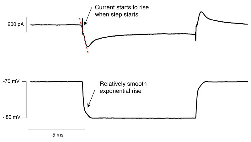
Finally, we have an approximately correctly set example. The important thing to note is that if you extrapolate backwards from when the rising phase of the transient, it intersects with the baseline current at the moment the voltage step begins (red dashed line). In this particular instance, there is a small instantaneous rise, but this is probably the remnants of uncompensated pipette capacitance. When you are there doing it for real, and you’re looking for this point where the extrapolated current intersects with baseline, it’s pretty easy to tell the difference between a little bit of pipette capacitance and big instantaneous rise shown in figure 6.
So, in conclusion:
- When you perform whole-cell correction, i.e. dial in the series resistance and whole-cell capacitance, you are NOT improving your voltage clamp, you are just subtracting off the current needed to charge the membrane capacitor.
- However, it is important to perform whole-cell correction properly as the values you determine are used to perform series resistance compensation.
- Your best approach is to estimate the series resistance by dividing the size of your test pulse in mV by the peak amplitude of the capactive transient. Then dial that in and start increasing the whole-cell capacitance until the extrapolation of the remaining transient looks like it intersects the holding current at the moment the test pulse starts.
Note 1. When you are performing voltage clamp, you often need to step the cell you’re recording from to a new voltage. When you do this, you need to charge up the capacitance of the cell membrane. Your ability to charge up this membrane capacitor is limited by the resistance of your electrode and the junk in its tip from when you went whole-cell, i.e. your series resistance (Rs). The lower the Rs, the more current your can pump into your cell, and the faster the membrane potential (Vm) approaches your command potential (Vcmd). While you essentially always want as low Rs as possible, it a low Rs can come with a downside: that initial inrush of current when you try to step the potential can saturate certain electronics inside the amplifier (the primary operational amplifier responsible for voltage clamp). When you correct for whole cell parameters, you pass the job of charging up the membrane capacitor to another operational amp, freeing up the primarily operational amplifier to pass current in response to ion channels. Not only does this minimize the risk of saturating the primarily amplifier, but the values are used to perform series resistance compensation.
This is really a great resource!
Thanks a lot for bringing this together so clearly.
One thing that I was confused about for a long time is online-vs-offline correction of R_s. It seems like some hardcore biophysical studies (just from the top of my head: Meyer, Neher, Schneggenburger, J Neurosci. 2001) consciously avoid correcting for all of the measured R_s online and rather leave a specific residual that is then corrected offline.
To my understanding this, this largely fixes the low-pass filtering issue, but not the VC issues associated with lack of R_s correction.. But I also understand that for EPSC recordings they wouldn’t do voltage steps, and that principal MNTB neurons are quite compact and these are also pretty low R_s recordings anyways. So I am unsure how to decide which value for uncompensated R_s is appropriate for which conditions.
Do people patching different cells have a good heuristic what the uncompensated R_s should be?
Hi Habakuk,
Great question. So let’s start with the specifics. So you’re talking about the paper https://doi.org/10.1523/JNEUROSCI.21-20-07889.2001 ? So they certainly did perform Rs compensation, they have a beatifully written section in the methods. “. Second, the electronic Rs compensation of the amplifier was set such that the uncompensated fraction of Rs did not exceed 3 MΩ, and recordings with measured Rs of >10 MΩ were excluded from the analysis” So their procedure is that they didn’t use any cells were Rs was greater than 10 MΩ. So lets say they got a 9 MΩ Rs recording. Then they had to be able to compensate up to at least 66%, to get the uncompensated fraction of Rs to 3 MΩ. Then they used the very simple algorithm as laid out in Traynelis 1998, J Neurosci Methods, to calculate the expected EPSC size given an Rs of 3 MΩ, the calculated capacitance and estimated reversal potential. They were able to do this because they assumed that the AMPA current is linear with voltage, i.e. it followed the simple law I = G * (Vm-Ve). And they could calculate all of those accurately by knowing the voltage drop over the series resistor.
So, on to the generalities: How do you know how much uncompensated R_s is appropriate? Well the always true answer is, “as little as possible”. But in practice, it’s always about what you are measuring. You can always make a nice steady state estimation of for voltage error by looking at Rs*Ihold. It is often the case that it is the variance in your steady state voltage error that is a bigger problem, than the absolute size. If it’s something like 10 mV (10 MΩ * 1 nA) in one recording, but 1 mV in another (2 MΩ * 500 pA), then that’s 10 mV of added error to your measurement of a reversal potential [roughly speaking]. Those were quite leaking cells, (1 nA of holding current often means you’re cell is toast). However, if you get into a cell with a him membrane resistance and you’ve got 5 pA of holding current, your steady state error is always going to be negligible. However, the temporal quality of your voltage clamp might still leave a bit to be desired, i.e. you might only have voltage clamp at steady state. You can go to my post here and see what happens, but roughly, the corner frequency of the filter set up by Rs and Cm is given by 1/2*pi*Rs*Cm … So if you’re trying to voltage clamp something fast, and your cell has more than a few pF of capacitance, then you need to have very low series resistance.
So think about what you’re measuring. What errors are acceptable to you? Then figure out given your system, how you can keep your errors under that, and set your thresholds appropriately. But if you REALLY didn’t want to do that [which would make me sad], then make sure Rm/Rs is greater than 10, and make sure Rs * Cm is less than 100 microseconds. That will put you in good steady to measure everything but sodium currents.