For my first post I’m going to gift to you knowledge of what may be the single most useful circuit you will ever see. I have made over a dozen of these for various people, and its uses are never ending. Do not be scared if you’ve never made a circuit before. This is so simple. And you will feel like an absolute master when you’ve finished it.
I give you, The Triggerer
This is extremely useful for triggering old Grass stimulators that do not take TTL triggers (S44s need +15 V at the STIM pin and +7 V at the DELAY pin; S88s need 7V). It’s great for triggering high power LEDs and for activating solenoids and valves. Basically, if you want to trigger something with your TTL out, this is a cheap, simple method.
First, why do we need to do this? Three reasons. Firstly, a TTL pulse is a ~5 volt pulse. This is all it is. I’ve known people who get confused and think that “digital” pulses are somehow made from different electricity from analog signals. They’re not. It’s just a 5 volt signal. But sometimes, you need more voltage than this to trigger something else, this circuit allows you to step it up. Secondly, your TTL trigger cannot deliver much current (usually not much more than 100 mA) so that rules out anything that needs much power (5V at 100 mA = 0.5 Watts). If you try to draw more current than that (that is to say, your “load”, i.e. the device you’re trying to trigger, presents a low resistance) you can damage whatever is generating your TTL pulse. Thirdly, capacitance and inductance. These two features present opposite, but equally nasty effects. If your load has a big capacitor in it (like a really long coax cable) when you try drive the TTL high, the capacitor will take some time to charge up to 5V because your TTL pulse can’t pass much current, meaning your signal will be delayed. On the other hand, if you have an inductive load, for instance any valve, solenoid or motor, when you try to turn off the TTL pulse you can get HUGE voltages built up over the load, which can seriously damage circuits. This wonderful circuit deals with all these problems at once, as it in essence works as an amplifier and isolator at the same time.
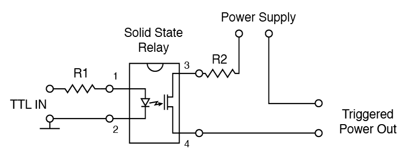
How does the circuit function? Well it is incredibly simply. The magic is the Solid State Relay (SSR). It functions just like a mechanical relay, but with no moving parts. Your TTL pulse causes current to flow between pin 1 and 2 of the solid state relay (though not too much, thanks to resistor R1) This causes an LED inside the SSR chip to light up. This light activates a photodiode inside the chip, which in turn activates MOSFETs inside the chip, which is situated between pins 3 and 4. The MOSFETs go from having a very high resistance (>1 GΩ), to very low resistance (<20 Ω), and this allows power to flow from the power supply into whatever you are triggering. The maximum amount of output current is decided by R2. Note the important features of the circuit here:
- Your TTL pulse needs to supply enough current to light up the LED inside the SSR, but not so much to blow up the LED.
- The voltage supplied by the power source is presented at the trigger terminals.
- There is NO electrical contact between the input side and the output side.
My circuit has no part numbers. This is where you need to make your design decisions. You choose your SSR based on the voltage and current you need. I’ll show you how, it is usually pretty simply. Let’s say you need to trigger an air puff, so you’ve bought one of Clippards excellent 3 way 12V valves.
Step 1. Figure out the voltage.
It needs 12 volts. That was easy. So we need to make sure our relay can gate more than 12 V.
Step 2. Figure out the current (and resistance).
For whatever reason these places hardly ever tell you how much current their parts want, or even resistance they have; they just tell you the power they draw. In this case 0.67 Watts. We know P = I × V, so I = P/V which in this case is 0.67/12 = 55.8 mA. Let’s put in a nice safety margin, and say we might want to deal with 200 mA. At the same point, we can calculate the effective resistance of our load, R = V/I = 12/0.0588 = 204 Ω, which will be useful later.
Step 3. Figure out which SSR we want.
I like to search for things on Farnell.com. You don’t need to buy from there, but their search engine is good. Go there and search for Solid State Relays, and chose MOSFET ones. We can limit our search to load voltages at least more than 12 V, load current more than 200 mA, and we want a Single Pole – Single Throw – Normally Open configuration (SPST-NO). Finally set relay terminals to “through hole”, for easy soldering. It should return a bunch of options, most of which will be fine. If you rank it by price a few options, but somewhere near the top should be the PVA1354NPBF, which I nearly always use. If we check out its datasheet we see everything we need to know. It needs ~20 mA to turn it on (Fig 2 and 7). It tells you that when you drive 20 mA its resistance drops to 5 Ω (“Maximum On State Resistance”). We can also see that the maximum load current it can gate is 375 mA. We also see that it can gate more than 12 V (“Operating Voltage”). Finally, it tells us that that the time it takes to switch the relay on and off are 30 and 15 µs respectively. The only thing it doesn’t tell you is that the LED in the chip will have about 1.2V across it when 20 mA is going through it.
Step 4. Calculate the values for R1 and R2.
Our TTL pulse is 5 V, and we want 1.2 volts across the LED, hence we want 5 – 1.2 = 3.8 V across R1 when 20 mA is flowing. So R = V/I, R1 = 3.8/0.02 = 194 Ω. On the output, we’re trying to make sure we can’t pass more than the maximum current in the case that we accidentally short out the output. As the resistance of the SSR, and R2 are in series, we can add them, lets call this summed resistance RT. So when 12V is placed across RT we want the current to be less than 375 mA. So RT = 12/0.375 = 32 Ω. With the on state resistance of the relay being 5 Ω, that means R2 = 27 Ω.
We can check that this wont affect our output too bad. When we the relay is on, the supply voltage will be placed across R2, the on-state resistance and the load resistance, so 27 + 5 + 204 = 236 Ω. So the current through the load will be V/R = 12 / 236= 0.051 A, only a little bit below the recommended amount. Likewise, the voltage across the valve/load = I × R = 0.051 × 204 = 10.4 V, again, a little below the required voltage. Let this be a warning, if you absolutely need a voltage at the output, then you have to supply slightly more than that. This brings us to the nature of our voltage supply. You can use batteries or plug in DC supplies. Batteries are great, because you get 100% voltage isolation and zero electrical noise. However, most of the time you will need DC supplies, because the point of the circuit is that we need lots of power.
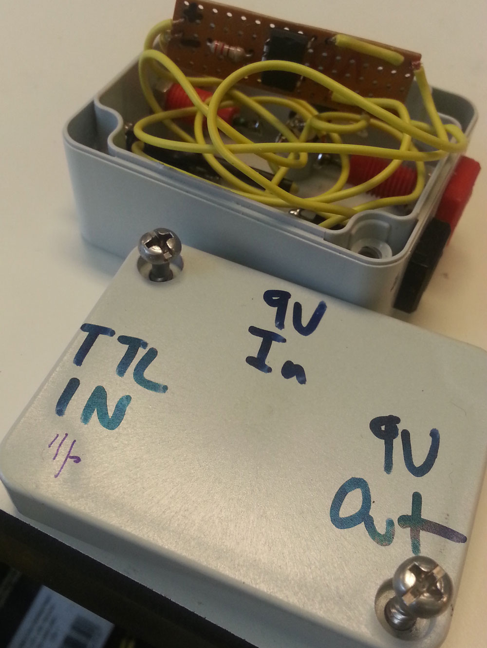
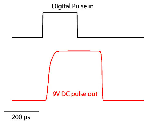
Now it’s just a matter of prototyping the circuit on a breadboard, then soldering it onto some perfboard. You wont be able to find resistors that perfectly match the calculated values. If you have to, use a resistor of too high a value for R1, as once you blow up the LED, the chip is done, while err on the low side for R2, as most chips transiently shut down when they pass too much output current, but start working again in a few seconds (In the above example, I bypassed R2 because it got deployed on something that drew more current that the original spec). Finally, you’ll make your life easier if you use a DIP socket to plug your SSR into, rather than solder the relay right to the board. Glue the board into a little enclosure, and add some BNC ports or 3.5 mm phono-socket or whatever you want for inputs and outputs, hook up the power, and you’re done. You don’t need an on/off switch, because the SSR draws almost no current when not being triggered. You should be able to make this less than $50, and less than $10 if you can find a DC supply lying around. You should expect behaviour like this:
Bill, I just found this website, and happened to see your comment that older Grass S88 stimulators require 7 v for triggering. **Thank you**!!!
Now, I’d like to get a negative pulse out of one of the two channels in this thing, for voltages up to -30 V. Do you know an easy way to invert the polarity on this beast?
I know your original comment is several years old, can you shoot me an email if you choose to respond, so I can look for it? Thanks!