 Sometimes you just need to get a notion about whether a signal is big, little or non-existent, rather than its exact value to 4 decimal places. In my case, I wanted a manometer, so I could tell how much pressure the students were apply by mouth when learning to patch cells. I could also imagine someone wanting to measure the DC value of a voltage that they were applying a digital high pass filter to, just to make sure it didn’t go out of the range of the DAQ. I’ve seen people use cheap multimeters for such task, In this case, I offer a solution, that is perhaps more modular, and certainly cheaper.
My sensor was a Freescale Semiconductor MPX5050DP pressure sensor, it puts out a voltage that maps in a basically linear fashion [room pressure to room pressure+500 mBar] to [0 Volts to Supply Voltage], e.g. basically 100 mBar a volt when given a 5 V supply. But the point here is that you can supply whatever voltage you want.
 The next step is using an LM3916 combined with a 10 segment LED bar, each of which was available for a pound. The block diagram on page 7 of the datasheet explains how the LM3916 functions beautifully: your analog signal is compared to a family of voltages generated internally in the chip by a resistor array. The resistor array splits the voltage between RHI and RLO pins into 10 even steps, thus you can alter the range and sensitivity of the output by changing the voltages at RHI and RLO. Typically you would have the maximum voltage you’re interested in at RHI, and then ground RLO.
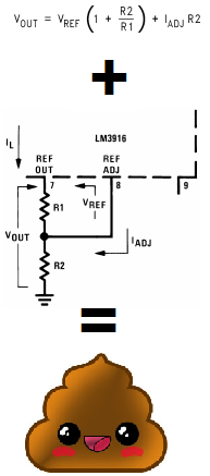
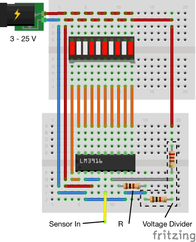
The data sheet has various equations explaining how the Ref Out and Ref Adj pins are supposed to work. And if you want, you can mess around trying to get them to work. However, I’ve got a shortcut. You can simply ground the Ref Adj pin and put a resistor of value R between Ref Adj and Ref Out. Keep the resistor above 1 kΩ, and then the current through each LED will be very approximately given 12.5/R, and I stress, very approximately. Then just make a voltage divider somewhere else in the circuit to supply to RHI.
 The beauty of this circuit (especially when you perform the simplification above) is that it is incredibly easy to chain as many LM3916s and 10 Segment LED bar together as you want. Simply tie all of the Sig pins together and then daisy chain the RHI of one LM3916 to the RLO of the next, and give the final LM3916 your maximum voltage. This means that the internal resistor array of each chip combine into one giant one. You’re best to keep pin 9 of each pin held high, to keep to LEDs in graph mode. Again, there is information in the datasheet on how to do this daisy chaining “properly”, but I suspect after an hour of trying their way, you’re just going to give in and do it my way.