Impedance is a concept that some people say they understand, but deep in their heart of hearts they know they don’t. I’m going to try and help you get a more helpful conceptual understanding of it. But to try and entice you into learning about it, I’m going to pose you a question: where does a sine wave go, when it’s amplitude is zero?
People explain impedance in lots of ways, but the best way to get to grips with it is to realize that it is just the ratio of voltage to current over some circuit element. That’s really all it is. Honestly. But those of you who have learnt about it before might be saying “but Bill, aren’t there all kinds of imaginary numbers and complex exponentials and scary math when I deal with impedance?” To you I say, yes, there are, but so long as you’ve got a copy of Matlab (or Octave) lying about, it all gets super simple, super quickly. First I’m going to give you a non-rigorous, but hopefully quite intuitive math overview, and then I’m going to show you how to use it. So long as you vaguely grasp Matlab, and you know how to use Ohms law you’re going to be fine.
The Maths
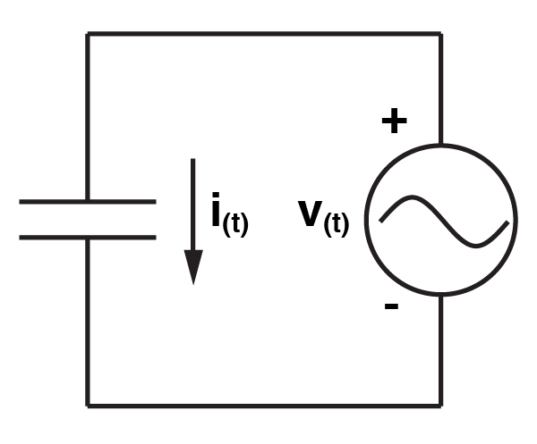 Let’s start with the circuit we’re going to analyze first. It doesn’t get any simpler, it’s just a capacitor with a sine wave of voltage going over it. So, we can say that the voltage over the capacitor is given by this equation:
V is the peak voltage. Omega, or ω is angular frequency, that is, if a signal makes one cycle in one second, it has an angular frequency of 2π. Now, the behaviour of a capacitor can be explained by the equation:
Or in English, the current through the capacitor is given by the rate of voltage change over the capacitor multiplied by the capacitance of the capacitor. Now, seeing as we know the function for the voltage (equation 1), we can calculate the rate of change, by taking its derivative:
If we then substitute that result into equation 2, we get the equation that explains the current
At this point, we should take a little pause, and think about what we have shown, because it isn’t insignificant. Because the voltage is a function of $latex sin(\omega t) $, while current is a function of $latex cos(\omega t) $, we can see that the voltage always lags behind the current by π/2. Furthermore, as the current is given by $latex V \omega C cos(\omega t) $, and we know the largest $latex cos(\omega t) $ can ever be is 1, then the largest the current can ever be is $latex V \omega C $. Now seeing as our goal is to find the ratio of voltage over current, we should already see that our answer is likely to be something like $latex \frac{v}{i} = \frac{V}{V \omega C} = \frac{1}{\omega C} $, the only problem with it is that equation doesn’t take care of the phase shift. 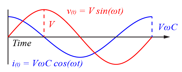
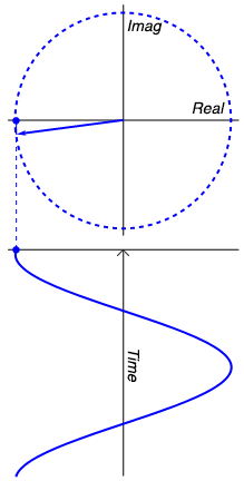 So, were do the imaginary numbers come in? Well they come in when we try to answer the question I posed earlier: where does a sine wave go when its amplitude is zero? The answer is: into the imaginary plain. The animation to the right probably explains it better than words can, but lets give it a shot anyway. But first, let me give you a motivating example. If I asked you, what is the amplitude of the sum of two sine waves with amplitudes of 2 volts, what would you say? You might instantly be tempted to say 4 volts, but then you’d realize that if the two waves were 180º aka π out of phase, you’d get zero volts. So obviously, when you’re doing maths with waves, phase is just as important as amplitude. Using complex numbers helps us keep track of the phase and actually can make the math easier. And it does it like this: Look at our sine wave over to the right, and lets imagine it is voltage. When it is at it’s positive peak, we can say it’s amplitude is 100% real. However, a quarter cycle later, the actual waveform has zero amplitude. Does that mean that the sine wave has really disappeared? No, it is still very much capable of doing work. So now we can say its amplitude is 100% imaginary. As the wave continues, the real and imaginary component of its amplitude vary, and at any point we can calculate the real portion ( $latex Re $) with $latex r cos(\omega t) $ and the imaginary portion ( $latex Im $) with $latex j r cos(\omega t) $ where $latex j $ is the imaginary unit, such that $latex j^{2}=-1 $ (I’m using j rather than i, because i stands for current). What is r? It is the magnitude of the signal, i.e. the radius of the circle that the sine wave is carving out. The magnitude of the signal is the same as the peak real amplitude of the sine wave, and can at anytime be calculated with Pythagoras’ Theorem, e.g. $latex \sqrt{Re^{2} + Im^{2}} $. Similarly, the signals phase can be calculated with simple trigonometry as $latex arctan(\frac{Im}{Re}) $. Thus the entire signal can be explained as the sum of the real and imaginary portions, that is:
But the point that you need to get is that there is no magic mathematical weirdness going on here. All the “imaginary” bit is trying to do give you a bookkeeping tool, so that you don’t mix up the magnitude and the phase of the signal. It is no more magical or strange than if I told you that a sine wave had an amplitude of X volts, and a frequency of Y Hz. For example I could tell you that a signal could be described by a vector $latex 3 + j4 $ then we can calculate its magnitude with $latex \sqrt{3^{2} + 4^{2}} = 5 $, and we can calculate its phase with $latex arctan(\frac{4}{3}) = 0.93 rad $. Importantly (you’ll see why soon), we can see that if we multiply the the vector by $latex j $, we “rotate” it by $latex \frac{\pi }{2} $ aka 90º. Proof? Well imagine a purely Real number, so it’s vector extends horizontally to the right. If we multiply it by j, it is now purely imaginary, so it’s vector points perfectly upwards. Multiply it by j again and the number becomes real but negative (j × j = -1), so it points to the left. Multiplying by j again gives us an imaginary but negative number, pointing down. And a final multiplication by j brings us back to where we starts (-j × j = -1 × j × j = -1 × -1 = 1).
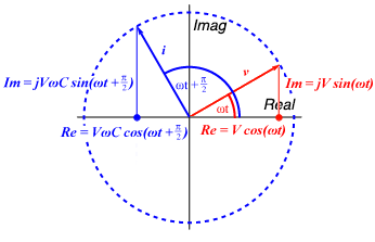 So given what we’ve already calculated about capacitors, we can use now complex numbers to represent the current and voltage over them. We can say the voltage across the capacitor is:
And we can say the current through the capacitor (remember, this leads the voltage by π/2):
As we’ve said, the goal is to calculate the impedance (Z), which we are finally in a position to do. Impedance should just be the ratio of the voltage to the capacitance, so:
Don’t believe that simplification? It works out, but you need to use Euler’s Formula, realize that $latex cos(x + \frac{\pi}{2}) = -sin(x)$, that $latex sin(x + \frac{\pi}{2}) = cos(x)$ and remember that $latex -\frac{1}{j} = j $. Importantly, notice that we’ve taken the definition of impedance we came up with earlier ($latex \frac{1}{\omega C} $), which was simply the ratio of the peak voltage to the peak current, and then divided it by j. Seeing as we’re going to use impedance like resistance, hence V/Z = I, we will end up doing the following:
So to convert voltage to current, we multiply the voltage by j (among other things), which as we’ve said rotates the vector by 90º or π/2. You see? The impedance of a capacitor is just the ratio of the peak voltage to the peak current, with a factor of j to remind you to rotate/shift the phase of the current by π/2.
The usage
So there is a chance that you didn’t follow all of that. Ultimately, it doesn’t matter. All you need to remember is that so long as you treat the impedance just the same way you treat resistance, you will not go wrong. Let me show you. Let’s start with the circuit above. Let’s say that voltage sine wave has a frequency of 1kHz = 2π kRad/s, and a peak amplitude of 5 mV. Finally, let’s say that the capacitor has a capacitance of 10 nF. So, in Matlab we say:
>> w = 2*pi*1000; %angular frequency
>> v = 5e-3; %peak voltage
>> c = 10e-9; %capacitance
Just as if the capacitor was a resistor we would say
Here we simply say:
As we know that
We can go into Matlab and type:
>> z = 1/(i * w * c);
>> current = v/z
>> current =
     0 +3.1416e-007i
Remember, this result is complex, so it retains the phase information about the current. If we wanted to know the magnitude of the current we could use Pythagoras as we did above, and to find the phase we could use trigonometry, but instead Matlab has built in functions which does exactly that.
>> phase = angle(current) % calculates the phase exactly as shown above
phase =
     1.5708
>> magnitude = abs(current) % calculates the magnitude exactly as shown above
magnitude =
     3.1416e-007
So the peak current is 314 nA and it is out of phase (unsurprisingly) by π/2.
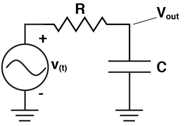 Lets do something a bit more exciting. Let’s analyse a simple low pass filter. Remember, we just treat the impedance of the capacitor as a resistor. If it was a resistor, we could calculate $latex V_{out} $ with the voltage divider equation and of course, we do just that:
Instead of calculating the behaviour of the circuit at a single frequency, lets calculate it across a range. Let’s assume the capacitor is 100nF, and the resistor is 1 kΩ. So, in Matlab:
>> f = 1:1:1000000; % frequency from 1 to 1,000,000 Hz
>> w = 2*pi*f; % Convert to Angular frequency
>> v = 5e-3; %Peak voltage
>> c = 100e-9; %Capacitance
>> r = 1000; %Resistance
>> z = 1 ./ (i * w * c); %Impedance
>> vout = (v*z)./(r+z);
And we’re done. We can see the outcome simply with
>> subplot(2,1,1); loglog(f,abs(vout)); title('Magnitude'); xlabel('Frequency (Hz)'); ylabel('Voltage (mV)');
>> subplot(2,1,2); semilogx(f,angle(vout)); title('Phase'); xlabel('Frequency (Hz)'); ylabel('Phase Offset (Rad)');
Which should leave you with something very much like the following, clearly showing how the filter suppresses high frequency input while also shifting the phase. 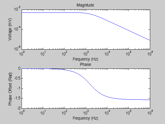
Finally, this whole post has been about capacitors. This is because neurons are capacitors. However, it is worth noting that inductors also have impedance. It would be good practice for you to go through and figure out the impedance of an inductor (it will require almost identical steps). But for references sake, the answer is $latex Z_{inductor} = j \omega L $.