Light is great stuff. It provides energy to the ecosystem stuff, preventing earth from being a blue and grey desolate rock, but more importantly, it is really helpful in the lab. I use it mainly in a beam break manner, so I can tell whether something is in a region of space, without touching it. But it can also be used to detect distance, movement, temperature and pretty much anything else you can think of, so long as you can detect the light accurately enough. And this is exactly what I’m about to teach you: how to detect light, amplify it, and make it work for you. The following circuit isn’t designed for ulta-high precision, but it can be made with less than 10 components, and only requires one design decision.
Your average two pin photodiode is basically made the same as an LED (in fact, if you can’t find a photodiode, LEDs will work too). However, as opposed to an LED, where charge dropping from one bit of the semiconductor to another releases a photon, in a photodiode, photons cause charge to move back up the energy hill. This charge will create voltages or currents if you want it to, but importantly, the amount of charge is linearly proportional to light intensity over a huge range of magnitudes. All our circuit needs to do is detect this charge movement, and amplify it appropriately.
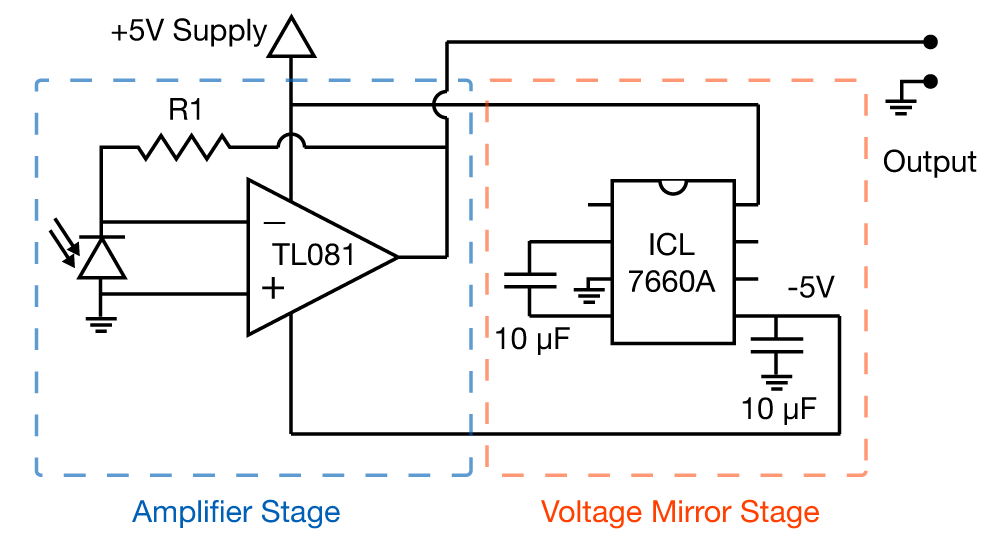
The circuit here has two stages, and I’ll address them in turn.
Voltage Mirror Stage
In order for this circuit to work in a simple and robust fashion, we need to create a negative voltage. We need this, because if you’re in a perfectly dark place, your amplifier might want to put out 0 volts, and amplifiers generally cant reach quite to their voltage supplies (e.g. if they were supplied with 5V and 0V, they might happily work in a region between 100mV and 4.9 volts). There are vast numbers of ways to do make negative voltages (and just as many ways to avoid having to) but to keep things simple, and importantly, modular, we have a stage that flips whatever you supply it with in the negative direction. This is achieved by one chip, the ICL7660A. If you make this circuit, I recommend buying a few of these guys, as they are useful whenever you want to work with op-amps. The datasheet is here if you want to know more, but the outcome is simple: Put your positive voltage in pin 8, ground pin 3, put a 10 µF capacitor between pins 2 and 4, another one between pin 5 and ground, and whatever voltage you put into pin 8, you get an equal and opposite voltage at pin 5.
Amplifier Stage
Now we have negative voltage, our op-amp will be simple to work with. The practicalities of op-amp use aren’t complicated: So long as you connect the output to the inverting input (negative symbol pin), whatever voltage you apply to the non-inverting input (positive symbol) will appear at the inverting input. Or put another way, the op-amp will do whatever it can to make sure the inverting and non-inverting input have the same voltage. In this circuit, the logic is as follows:
- Light falls on the photodiode, causing the photodiode to push positive charge to its cathode.
- This charge begins to alter voltage at the non-inverting input of the op-amp
- The op-amp output voltage increases until the current flowing across R1 is enough to oppose the current generated by the photodiode
So you can see, that as R1 gets bigger and bigger, the op-amp needs to make larger and larger voltages to create enough current to opposite the photodiode current. Here is your design decision. If R1 is too big, the amplifier will be too sensitive, “saturating” (providing maximum output) when there is only a tiny bit of light, so you lose all ability to judge varying amounts of light. Also, it will make your output noisy. On the other hand, if R1 is too small, you won’t amplify the light-induced current, and hence you might not be able to detect anything. My advice is to try somewhere between 100 kΩ and 10 MΩ, depending on your light intensity.
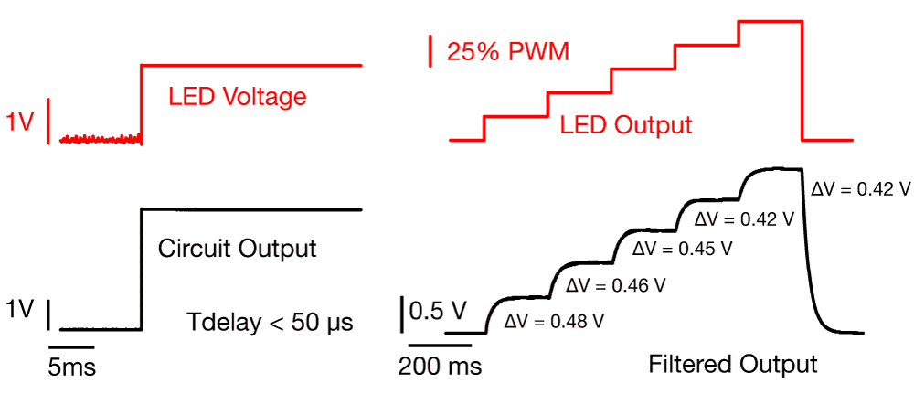
This circuit was made using a 10 MΩ feedback resistor. When I flashed an LED at it, there was no recordable lag between the voltage at the base of the LED (i.e. light onset) and the output voltage, so it works up to at least 20 kHz. If you feel like calculating the bandwidth of the amplifier, it’s given by the equation:
Where GBP is the Gain Bandwidth Product of the op-amp (basically the frequency at which the amplifier stops amplifying), which is the case of the TL081 isn’t available on its datasheet, however the Unity Gain Bandwidth is basically the same thing, which is 4 MHz for this amplifier. R is the feedback resistor, and C is capacitance in parallel with it. In this case, we don’t know what it is, as it’s just the stray capacitance of the circuit. However, I would be tempted to put a 1 pF capacitor across the diode, which would mean that this amplifier should have a bandwidth of 56 kHz. I say to put a capacitor in for two reasons: firstly, it will lowpass filter your output, getting rid of ripples in your output. Secondly, don’t kid yourself, even without the added capacitor, your circuit will not reach the 4 MHz bandwidth of your op-amp, there is stray capacitance, but at least if you supply the capacitor, you will know the limits of your amplifier, as opposed to guessing. The figure also shows that we’re getting pretty good linearity with light intensity. I used Pulse Width Modulation to get reliable light intensity differences, however, that meant I had to filter the output by putting a 10 nF capacitor in parallel with R1.
This amplifier will be perfect for beam break sensors, or for detecting the timing of light flashes. It can even be used to accurately detect the distance of an object with surprising accuracy. So long as the object is stereotyped, you can simply shine a light on it, calibrate the output by distance, and you’ve got a simple no-contact distance sensor. The result below was achieved by simply moving a sheet of paper towards the photodiode while an LED shone on it (my hands weren’t very steady, hence the wiggly line).

Can this circuit detect flickering of LED which is not perceptible by human eye?
Absolutely! In fact, it easily reports the flickering due to PWM on the arduino. You need to choose the feedback capacitor correctly, but otherwise it will be easily able to perform up to 10 of kHz and even 100s of them.
Hello,
I am working on a project on Visible Light Communication using Arduino UNO, can you help me in that? I am planning to use PWM modulation and Manchester encoding technique, bu i have no clue how to implement both on Arduino.
Hi,
I’m not 100% sure what you mean by PWM and Manchester encoding. PWM is access directly in arduino with the analogwrite() command. Manchester encoding is not natively supported by the arduino IDE, however, there are several libraries out there, like this one though I’ve never used it personally. It doesn’t strike me that it would especially hard to write a little function that took a binary array as an argument and then output it on a digital pin, after all, for each element in the array, you only have two cases to consider: 1 or 0.
Hello Bill,
Thank you for this post. This is very useful! I just had a clarification to make:
In the “Voltage Mirror Stage” section, you say “whatever voltage you put into pin 8, you get an equal and opposite voltage at pin 8.” I don’t understand this. I gave it a bit of thought, and perhaps the output “opposite” voltage is obtained at pin 5, but I am not sure. Could you please clarify this?
Also, I wanted to ask a couple of electrophysiology-related questions which don’t quite fit into the comments section of any individual post. It would be nice if you added a “Contact Me” section or a “General Discussion” post of sorts, to facilitate these kinds of discussions.
Kudos to you. This is a very useful blog! Thank you for your efforts.
Best,
Aalok.
Thank you Aalok! You’re absolutely right, I made a typo there (and a few in a couple of other places). Thanks for pointing it out. I’ll send you an email (and add an email address to the about me section).
Thanks a million!
Cheers,
Aalok.